
Flash in the industry: what should you look out for?
If just a few points are borne in mind, the use and integration of a flash lighting system is just as straightforward as installing a continuous or pulsed lighting source:
1. Synchronising strobe with image acquisition
When integrating strobe lighting, the most important task is synchronising the strobe system and the image acquisition system. The lighting system generates a very high-energy flash of light in a moment of time no longer than 220 µs. Capturing all of this light requires the precise coordination of image acquisition with the flash from the lighting system. One approach would simply be to set the camera’s exposure time long enough to ensure that the strobe occurs within this window of time. However, to do so would nullify all of the benefits related to eliminating ambient light and motion blur. This is why it is important to match the camera exposure time both in terms of duration and the moment it is triggered to the strobe lighting: if the flash length is 220 µs then the camera exposure time must also be 220 µs.
To achieve this in practice, many camera makers offer a high-priority flash output interface. Assigning the flash output the highest priority ensures that the flash signal is always sent synchronously with image acquisition, and delays due to other processing tasks in the camera are not possible. If this priority is not set, the lighting system could receive its signal later than image acquisition. In this case, the image would not be sufficiently lit – if at all.
Unlike standard PLC outputs, a specialised flash output of this kind has also been optimised in terms of its signal quality. Both jitter and tolerances in trigger timing are minimised so that they have virtually no influence on the signal path.
Depending on the camera type, the lighting is then connected to the camera and the specific settings are configured in the controls. If you have any queries about connecting LUMIMAX® LED Lighting to your camera system, please contact us for assistance.
2. Assessing motion blur from the speed of the test object and the length of the flash signal and exposure time
Motion blur in the final image depends both on the object (or conveyor belt) velocity v and the duration of the flash t. By inputting the maximum motion blur allowed in the image and the velocity, you can then calculate the maximum flash duration tmax.
To do so, first calculate the permitted object displacement, i.e. the distance that your test object can move during image acquisition before exceeding the level of blur allowed in the image.
Example:
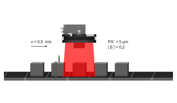
A printed code needs to be scanned on a drug product packaging. The product pack is moving at 0.5 m/s on a conveyor belt. The image scale is |β'| is 1:5. In the image sensor used PX', the width of a pixel is 5 µm. The maximum level of blur in the image is set at 2 pixels.
The maximum object displacement lmax in the image is calculated as follows:

By taking the maximum object displacement permitted and the object speed, the maximum flash duration tmax can now be calculated.
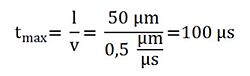
Using an exposure time/flash duration of 100 µs will therefore ensure that the object is not shifted by more than 2 pixels in the final image.
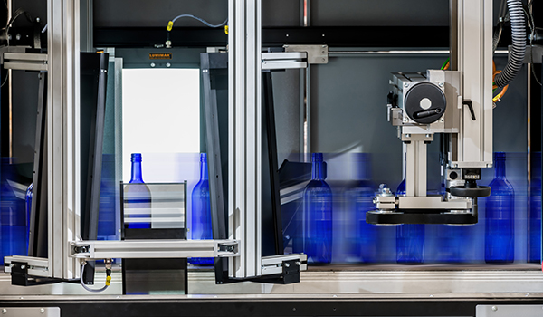
This case study is illustrated in the following video:
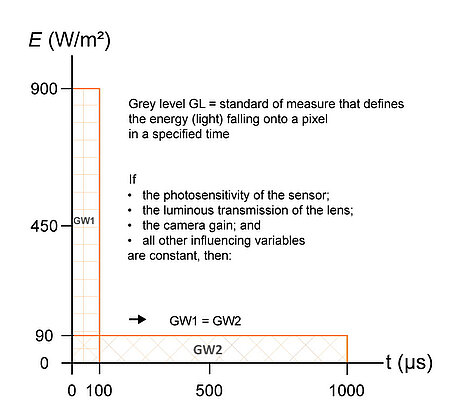
3. The interplay of irradiance and exposure time
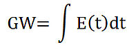
Especially in lab work, continuous-mode lighting tends to be used first. If a decision is then made to switch to flash lighting when integrating with the plant, the question then arises about the flash time t to set to achieve the right level of brightness. Assuming that all other settings remain the same – such as the photosensitivity of the sensor, the luminous transmission of the lens and the camera gain – then this can be calculated by using the factors of irradiance Ε(t) and grey level GL:
Example:
In continuous mode, a test object was lit for 2200 µs with an irradiance of 90 W/m².
In flash mode, the identical test object is also to be imaged. The grey levels in the object image should match those obtained in continuous mode. To meet this specification, we need to calculate the factor by which the irradiance needs to be increased when operating in strobe mode.
If we assume an exposure time of 220 µs, then we obtain the following ratio:
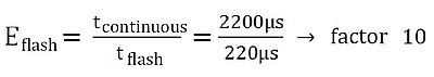
The strobe lighting therefore needs to be ten times brighter than the continuous lighting. If this can be guaranteed, then use of a flash lighting system is possible without having to compensate for a loss in image brightness.
If the three factors mentioned are considered when designing an appropriate flash lighting system, this will simplify integration with the plant. In addition, almost all of the LUMIMAX® LED Strobe Lighting Systems have a special feature that also simplifies their installation into a machine setup – namely an integrated strobe controller. This guarantees the maximum level of safety and functionality, shortens integration time with the Machine Vision system and ensures no power losses due to long cables between controller and lighting. The integrated controller also saves space and cuts costs since there is no need to use an additional module.

The extensive range of optical, electrical and mechanical accessories for LUMIMAX® LED Lights also simplifies both modification work to suit customer-specific requirements and integration with the machine environment. These innovative solutions enable quick and easy integration of LUMIMAX® LED Lights within a small footprint. With the special T-adapter cable, the lighting can be connected directly to the camera system, from where it is then controlled. This saves on additional wiring effort while simplifying component commissioning. The adapter cable is located between the camera’s electrical connection and the power supply. This is used to couple the lighting system directly into this signal flow, so it can use the camera both as its power supply and the trigger signal source. This reduces system design and installation work, ultimately achieving significant cost savings.
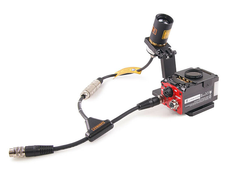
The LUMIMAX® Mounting Solutions enable the direct mounting of the High-Performance LUMIMAX® Lighting Systems to the camera series Cognex, Baumer, Keyence, SensoPart and Siemens. The mounting variations can be individually adapted and flexibly expanded, so as to ensure the exact adjustment of lighting angles and working distances. As an end result, the lighting, optics and camera form a single, compact unit.