
In tomorrow’s state-of-the-art, fully automated facilities, products control their own manufacturing process. With the aid of machine-readable product labelling, innovative tracking procedures enable the optimisation of manufacturing processes, machine capacity utilisation, costs and product quality. Yet the vision of ‘Industry 4.0’ depends crucially on the communication between product and machine. Only a high-quality product code can guarantee a smooth, error-free flow of information. Thanks to Machine Vision-based code verification, potential problems are resolved before they even occur. In a ‘smart’ factory, the products communicate directly with the machinery. Via its product code, the product itself tells the system which step must be performed next. And thanks to the information obtained, the complete production process can be tracked for each individual product. This ensures optimal process flow control.
Nor does the versatility of product label applications stop at process optimisation and quality inspection: a Data Matrix Code can also be used to provide the end user with all of the information that they require. Product traceability is another area that is now increasingly important – such as for combating counterfeit pharmaceutical products, for example.
Yet the proper functioning of these kinds of systems is dependent on the reliability of product code scanning. Direct Part Marking (DPM) codes are especially durable and long-lasting. With DPM technology, the machine-readable code is marked directly and permanently on the product. Additional product labels are no longer necessary.
The quality of the code is then verified using standardised procedures: ideally, this takes place in the plant directly after marking and then whenever the mark could be later affected. Trend analysis is used to ensure that the marking process proceeds without errors at all times. If the quality of a marking system starts to decline, this problem can be caught early before the mark actually becomes illegible. Right from the outset, this avoids time-consuming rework – or scrapping, in the worst case. The verification procedure guarantees the 100% legibility of the code throughout the entire production process – and beyond. To execute the reading and verification process in line with the standards, the lighting situation is determined alongside camera and software factors.
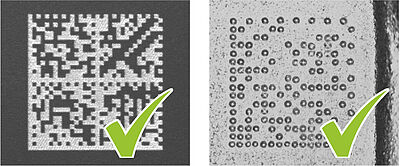
A standard-compliant set-up usually requires a 90° viewing angle for the camera and thus the camera must be positioned vertically to the test piece. Changes to this viewing angle would cause axial unevenness in the code and thus lead to a poor result in the quality assessment.
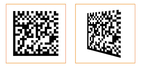
Left: code correctly imaged at a 90 ° viewing angle, right: code skewed by a change
to the viewing angle
The standards
The standards ISO/IEC 15415:2011/ 15416:2016 and ISO/IEC 29158:2020 are particularly interesting when it comes to the standard-compliant reading and verification of codes.
ISO/IEC 15415:2011/ 15416:2016
ISO standard 15415:2011/ 15416: 2016 relates to printed codes on labels and similar.
ISO/IEC 29158:2020
In contrast, the DPM standard ISO 29158 is used for direct part marking (DPM) and, for instance, also applies to lasered and needled codes on various surfaces.
The framework for verifying DPM matrix codes is provided by the standard ISO/IEC 29158:2020 (AIM DPM). For printed codes, the standard ISO/IEC 15415:2011/ 15416:2016 is referenced.
Apart from verification criteria and procedures, the standards also define the exact parameters for image scanning. This ensures that the code is not compromised by the components selected. According, the design of the Machine Vision system is not based solely on the part substrate but also on the specific characteristics of the marking or print system utilised.
When selecting a Machine Vision system, the lighting system has an especially important role to play.
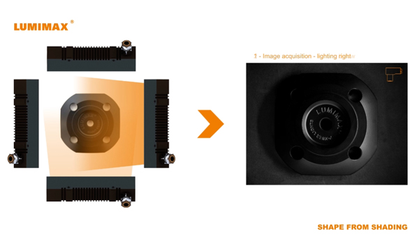
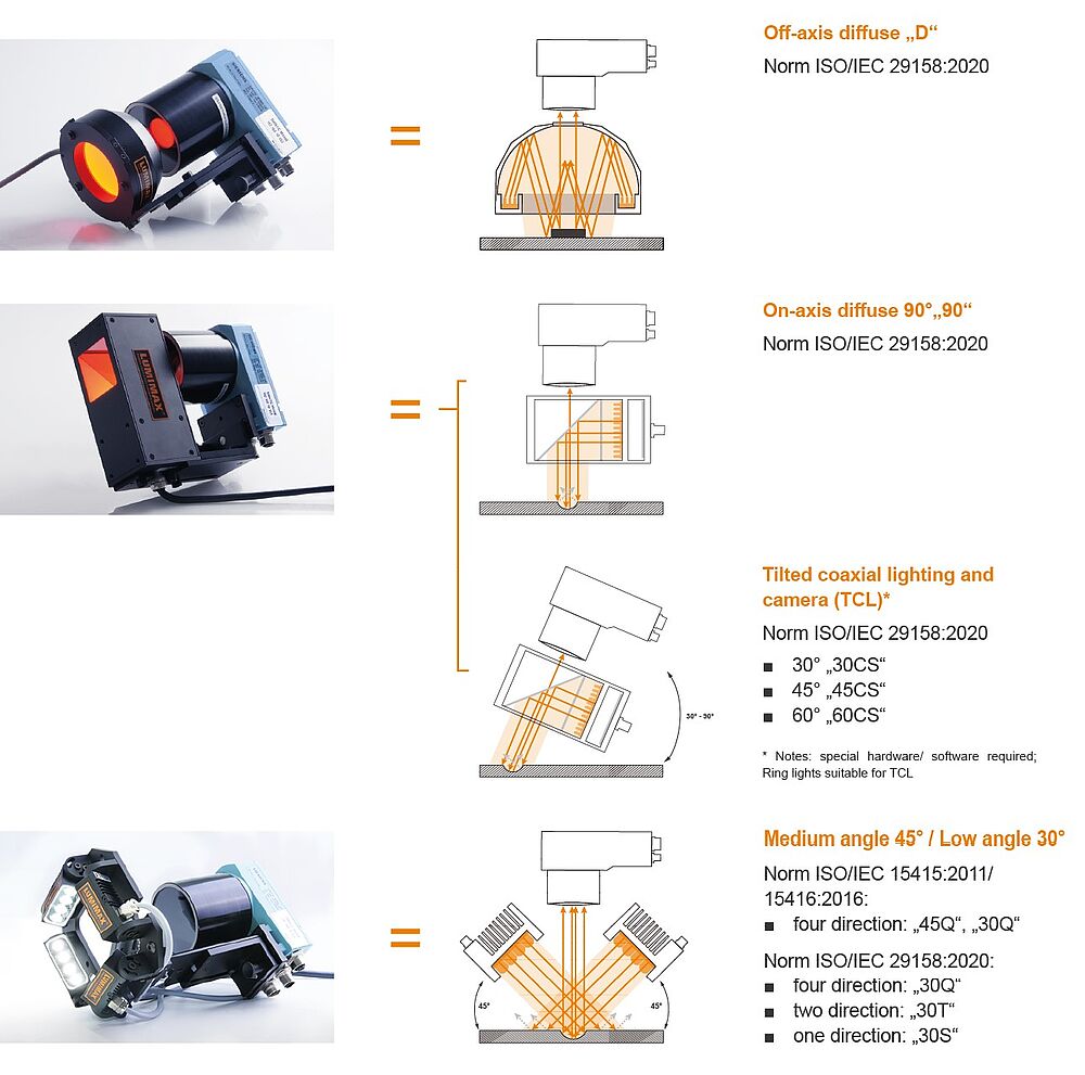
Depending on the standard applied, three separate lighting arrangements are permitted: an arrangement of 1, 2 or 4 lighting systems at a 30° or 45° angle. For very shiny or reflective surfaces, a coaxial lighting system or even a dome lighting system can also be deployed.
4 directions; right: diffuse coaxial reflected lighting
The ISO/IEC 15415:2011/ 15416:2016 standard defines three lighting versions for the standards-compliant reading and verification of codes, whereby four lights arranged in a square at an angle of 45° to the surface are defined as standard lighting. Depending on the application, however, the angle can also be reduced to 30° to the surface.
Under special conditions – such as for glossy and reflective surfaces – diffuse lighting is also permitted, which is then positioned once again at a 90° angle to the object. The light field is thus parallel to the surface. Coaxial reflected lighting is used for these applications. With this type of lighting, a diffuse, homogeneous light source is mounted over a semi-transparent reflector directly in the lens beam path. This provides very homogeneous, shadow-free lighting for the object.
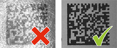
Right: needled code on cast metal
In contrast to ISO/IEC 15415:2011/ 15416:2016, ISO/IEC 29158:2020 permits additional lighting setups for directly marked codes. Among other things, the standard setup of four lights arranged in a square is expanded to include variants with two lights opposite one another and a single light. The angle of 45° to the surface can be changed depending on the application, e.g. to 30°.
Depending on the material and shape of the test piece, a suitable version can be determined here:
- plane, matt and rough surfaces: four-sided lighting arrangement
- curved and rotationally symmetrical surfaces: two- or one-sided lighting arrangement
- glossy and reflective surfaces: Coaxial or dome lighting
- glossy surfaces with a complex structure: Dome lighting
Simple integration

The lighting system and its setup for the test object is an important factor for the standards-compliant reading and verification of codes. To ensure the standards-compliant, reproducible and simple integration of lighting into the plant environment, customers can rely on the LUMIMAX® Mounting Systems.
One interesting option for mounting a coaxial or dome lighting system is offered by the LUMIMAX® Verification Adapter. This is used not only to mount the lighting directly on the camera system but can also pivot the lighting in and out in a predefined manner. This permits the optimal configuration of the camera, optics and lighting, and the protective tube can be mounted at the end, without any settings needing to be changed. To do so, the lighting is simply pivoted out and the protective tube is easily affixed. The lighting is then pivoted back into the exact position as configured earlier. The LUMIMAX® Verification Adapter also ensures a reproducible setup across all reading units.
An innovative mounting system is also available for the LUMIMAX® Miniature Bar Lights in the LSB series. These can be installed as a four-, two- and single-sided lighting system within a mounting bracket. To ensure the Bar Lighting System has a standards-compliant 45° and 30° angle to the surface, mounting points are already marked with which a standards-compliant setup can be guaranteed. The incident angle can also be altered between 0° and 90° in steps of 7.5°. This Mounting System can also be attached to the LUMIMAX® Verification Adapter, so as to ensure the lighting system can be simply pivoted into and out of a predefined, standards-compliant position.